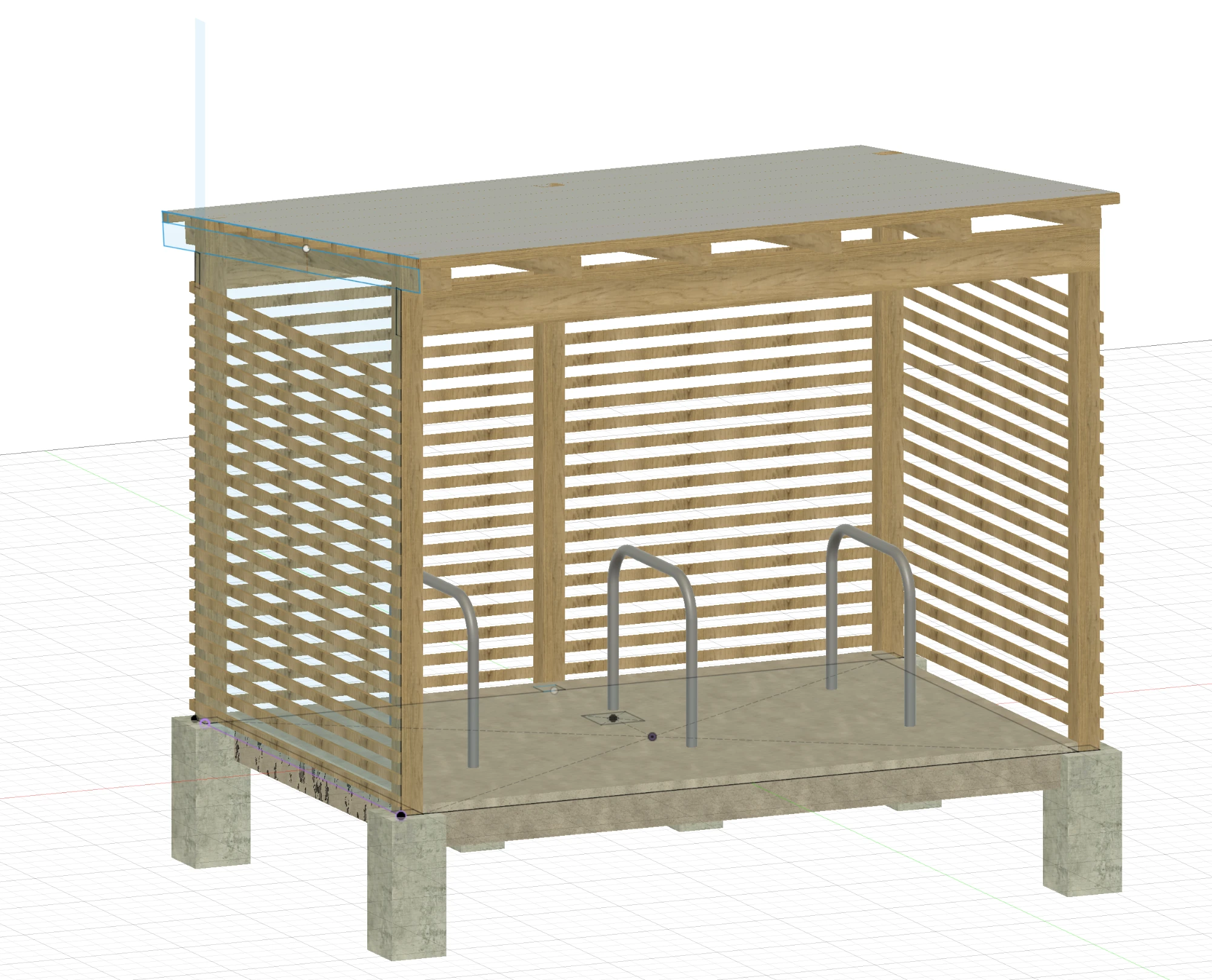
Six-bike open-fronted shelter with Sheffield stands, gravel-grid floor, slatted sides and corten steel roof.
Non-negotiables
Check these before and during the build:
No post at mid-front. The 3000mm front opening stays completely clear.
Stand and post concrete must finish fully buried (stand pockets min 50mm below top of MOT).
Purlin centres 300mm MAXIMUM — the 1.5mm flat roof sheet needs this support.
All roof fixing holes drilled 1.5–2mm oversize; EPDM washers snug, not crushed.
All heights measure from FFL = finished top of gravel. Agree the datum before digging.
3D model
Loading model…
Drag to spin, pinch to zoom. Switch off the roof sheet, slats or floor to see the frame and the concrete. The model is illustrative only: set out from the figures and written dimensions, not from the model.
An open-fronted timber-framed shelter for six bicycles, approximately 3000mm wide × 2000mm deep internally, with a mono-pitch corten steel roof falling to the rear. Bikes are secured to three galvanised root-fixed Sheffield stands set in concrete.
Front view: clear opening, three stands, slatted sides and rear.From below: rafters, purlins, post footings and stand-leg pockets.Looking up from the front: roof structure and footing positions.
Note on the renders: the 3D images show the ground cut away so the concrete is visible. In reality all concrete — post footings and stand-leg pockets — is fully below the finished floor and invisible.
Key dimensions
Item
Dimension
Internal footprint
3000mm wide × 2000mm deep
Front beam underside (headroom)
2050mm above finished floor level
Rear beam underside
approx. 1850mm above finished floor level
Roof fall
6–8° mono-pitch, falling to the rear
Roof overhang
approx. 150mm at front and sides, 100mm at rear
Sheffield stand spacing
3 stands at 1000mm centres, 500mm from each side
Overall height
under 2.5m at all points (permitted development limit)
Build instructions
Step-by-step sequence with drawings. Read alongside the Construction Specification — the spec governs materials and standards; this sheet governs order of work and dimensions.
Stage 1 Setting out and excavation
Set out the 3000 × 2000mm internal footprint with pegs and string (Fig 1). Square it by diagonals — both diagonals 3606mm. Agree position relative to the drive edge with the client before any digging.
Establish the datum: FFL (top of gravel) and mark it on a fixed reference. Every height in these instructions is from FFL.
CAT-scan the footprint. Excavate the whole area to 150mm below FFL.
Dig five post holes approx. 250mm dia × 600mm below FFL: four corners plus mid-rear, positioned so the posts sit just inside the internal footprint as Fig 1.
Dig six stand-leg pockets approx. 200mm dia × 300mm below formation (i.e. 450mm below FFL). Leg positions: stand centrelines at 500 / 1500 / 2500mm from the left wall; legs 750mm apart front-to-back, rear leg 600mm from the rear wall line (Fig 1).
Fig 1 — Setting-out plan. Tap to enlarge.
Stage 2 Concrete: posts and stands (same visit)
Set the five 100 × 100mm posts in postcrete, plumb both ways, braced, leaving tops long — they are cut to the roof line later. Keep faces aligned to the string lines.
Set the three Sheffield stands in postcrete against a string line: level with each other, vertical in both planes, hoop tops 750mm above FFL. The hoop plane runs front-to-back as the renders show.
Stop each stand pocket at least 50mm below the future top of MOT (i.e. concrete no higher than 100mm below FFL) so it ends up fully buried (Fig 2).
Leave all concrete to cure per the bag (minimum overnight; do not load posts for 24h).
Stage 3 Edging, membrane and sub-base
Fix 22 × 150mm PT gravel boards around the perimeter on 600mm PT pegs (pegs outside the boards), top edge exactly at FFL.
Lay geotextile membrane across the formation, lapped up the inside of the edging, slit neatly around posts and stand legs.
Spread and compact 100mm of Type 1 MOT in two 50mm passes with a plate compactor, finishing 50mm below FFL (Fig 2). This becomes the working platform for the frame — do NOT lay grids or gravel yet.
Fig 2 — Floor build-up (section). Tap to enlarge.
Stage 4 Frame
Mark the roof line on the posts: underside of front beam 2050mm above FFL; underside of rear beam 1850mm. This gives the ~7° fall (Fig 3).
Cut a 50mm deep housing (notch) into the top of each post so the beams sit IN the posts, bearing on timber. Do not face-fix the beams on screws alone.
Fit the front beam: 47 × 200mm C24 across the full front, overhanging ~150mm past each corner post. Fix with M10 × 120 coach screws through the housing.
Fit the rear beam: 47 × 150mm C24, housed into the two rear corner posts and the mid-rear post.
Cut post tops flush to the roof slope.
Fit six 47 × 100mm rafters flat-span front-to-back at 600mm centres (one at each edge), overhanging 150mm at the front and 100mm at the rear. Fix to both beams with structural framing screws or angle brackets at every bearing.
Fit 47 × 50mm purlins across the rafters at 300mm MAXIMUM centres, including one under the roof-sheet lap line and one at each sheet edge (Figs 3 and 4). Purlin ends may run slightly past the side rafters as a detail, per the renders.
Fig 3 — Section through shelter (front at left). Tap to enlarge.
Stage 5 Roof (corten, client supplied)
The 1.5mm corten sheet is the waterproof layer — there is no deck or membrane beneath it. The support centres, lap and fixing details below are what make that work; please query rather than vary them.
Cut Sheet B down to approx. 3000 × 1000mm (jigsaw with metal blade, or grinder with fine cutting discs, against a clamped straightedge). Cut edges need no treatment. Sheet A stays full size, 3000 × 1500mm.
If anti-condensation fleece has been supplied, apply it to the undersides of both sheets now, on the ground.
Lift and fix Sheet B (rear, LOWER) first: top edge to the rear, flush with the outer face of the side slat line each side. Two-person lift; sheets are ~35–53kg with sharp edges — gloves.
Run 50mm butyl tape continuously along Sheet B's front edge zone, then lay Sheet A (front, UPPER) lapping OVER Sheet B by minimum 150mm, with the lap landing on a purlin (Figs 4 and 5).
Fix with stainless self-drilling screws and bonded EPDM washers: into every purlin at 300mm centres along all four edges and along the lap; 600mm grid across the field. Drill every hole 1.5–2mm oversize first; washers snug, not crushed (Fig 5).
Fit the front-edge stiffener: folded corten drip edge if supplied, otherwise the 40 × 3mm flat bar screwed along the underside of the leading edge.
Fig 4 — Roof plan and sheet layout. Tap to enlarge.Fig 5 — Sheet lap and fixing detail (section, front at left). Tap to enlarge.
Stage 6 Cladding
Clad both sides and the rear with 18 × 44mm PT slats, horizontal, at approx. 50mm gaps, from ~150mm above FFL up to the underside of the beams (per renders). Stainless or coated exterior screws, two per bearing.
Keep the bottom slat clear of the gravel so timber is not sitting in standing water.
Stage 7 Floor finish (last)
Lay the plastic gravel grids over the compacted MOT, cut around posts and stand legs with a hand saw or jigsaw.
Fill with 10–20mm angular gravel, finishing 5–10mm proud of the grids and flush with the edging boards. Done last so the floor is not trampled during the frame and roof stages.
Sign-off checks
Before leaving site:
Ticks are kept on this phone only.
Any conflict between site conditions and these drawings: phone the client before improvising, particularly on anything in the non-negotiables at the top of this page.
Construction specification
Covered Bicycle Shelter — Construction Specification. Prepared: July 2026 · Location: front garden adjacent to gravel drive, Oxford
1. Project overview
An open-fronted timber-framed shelter for six bicycles, approximately 3000mm wide × 2000mm deep internally, with a mono-pitch corten steel roof falling to the rear. Bikes are secured to three galvanised root-fixed Sheffield stands set in concrete.
The floor is compacted Type 1 sub-base with plastic gravel grids and angular gravel. Two sides and the rear are clad with horizontal timber slats; the front is fully open with a clear (unobstructed) 3000mm opening — no mid-front post.
The client will supply the corten steel roof sheets (2 no. sheets, 3000 × 1500 × 1.5mm) and all construction materials on site. Client will provide skip.
Ground is sandy soil adjacent to an existing gravel drive. Free-draining; no services in the footprint.
Access for materials is via the drive. Skip is available adjacent for spoil and material storage.
The finished gravel surface should visually match the existing drive gravel where practicable.
3. Groundworks and floor
Mark out the 3000 × 2000mm footprint. Confirm setting-out with the client before excavation, including exact position relative to the drive edge.
Excavate the full area to 150mm below finished floor level. Remove spoil off site or as directed.
Excavate post holes for five roof posts (100 × 100mm posts, holes approx. 250mm diameter × 600mm deep): one at each corner and one at the mid-point of the rear edge. Note: no post at mid-front.
Excavate six holes for the Sheffield stand legs (approx. 200mm diameter × 300mm deep), positioned so the three stands sit at 500 / 1500 / 2500mm from one side wall, parallel to the front edge, approx. 600mm from the rear wall line.
Set the five roof posts in postcrete, plumb and braced, tops left long for cutting to the roof angle.
Set the three Sheffield stands in postcrete against a string line — level with each other, vertical in both planes, tops 750mm above finished floor level. Keep concrete at least 50mm below finished sub-base level so it is fully buried.
Fix 22 × 150mm pressure-treated gravel boards around the perimeter on 600mm pressure-treated pegs, top edge at finished gravel level.
Lay geotextile membrane across the excavation, lapped up the edging and slit neatly around posts and stand legs.
Lay 100mm compacted Type 1 MOT in two 50mm passes with a plate compactor.
Lay plastic gravel grids over the full area, cut to fit around posts and stand legs. Fill with 10–20mm angular gravel, finishing 5–10mm proud of the grids and flush with the edging.
Stands on site before excavation — hole depths to suit the actual root length supplied.
5. Timber frame
All structural timber to be C24 grade, pressure treated. All fixings galvanised or stainless.
Posts: 5 no. 100 × 100mm, concreted 600mm into the ground as Section 3. Cut tops to the roof angle once set.
Front beam: 47 × 200mm (2×8) spanning the full 3000mm clear opening, with approx. 150mm overhang beyond the posts at each end. Underside at 2050mm above finished floor.
Rear beam: 47 × 150mm (2×6), span broken by the mid-rear post. Underside at approx. 1850mm to give a 6–8° fall.
Beams to be housed (notched) into the post tops with a 50mm bearing and fixed with M10 × 120mm coach screws — not face-fixed on screws alone.
Rafters: 6 no. 47 × 100mm (2×4) at 600mm centres, front to back, fixed to the beams with structural framing screws, overhanging approx. 150mm at the front and 100mm at the rear.
Purlins: 47 × 50mm at 300mm centres, fixed across the rafters. A purlin must fall under every roof-sheet edge and under the sheet lap. Purlin spacing must not exceed 300mm — the 1.5mm flat sheet requires this support.
6. Roof — corten steel (client supplied)
The roof is single-skin flat corten sheet fixed directly to the purlins. There is no plywood deck or membrane; the sheet is the waterproof layer, which is why the support centres, fall and lap detail below must be followed exactly.
Sheets: 1 no. full sheet 3000 × 1500 × 1.5mm at the front; 1 no. sheet cut down to approx. 3000 × 1000mm at the rear. Cutting by jigsaw (metal blade) or angle grinder with fine cutting discs against a clamped straightedge. Cut edges need no treatment.
Lay the rear (lower) sheet first, then the front (upper) sheet lapping over it by minimum 150mm, with the lap landing on a purlin. Apply 50mm butyl tape between the sheets within the lap.
Fixings: stainless self-drilling screws with bonded EPDM washers, into every purlin at 300mm centres along all sheet edges and the lap, and on a 600mm grid across the field of the sheet. Drill holes 1.5–2mm oversize for thermal movement. Tighten washers snug, not crushed.
Front edge: fit a folded corten drip edge to prevent edge flutter.
Handling: full sheet weighs approx. 53kg — two-person lift with gloves; edges are sharp.
7. Side and rear cladding
Horizontal slats: 18 × 44mm pressure-treated battens at approx. 50mm gaps, fixed to the posts with stainless or coated exterior screws.
Coverage: both 2000mm sides and the 3000mm rear, from approx. 150mm above ground to the underside of the beams.
8. Materials schedule
Quantities are indicative; contractor to verify before ordering. Corten sheets are client-supplied.
Item
Specification
Qty
Type 1 MOT
Bulk bag (~850kg)
2
Gravel
10–20mm angular, to match drive; bulk bag
1
Gravel grids
Plastic paving grids, coverage 6m² + offcuts
as req.
Geotextile membrane
Non-woven, ~7m² incl. laps
1 roll
Gravel board
22 × 150mm PT, perimeter 10 l.m.
10 l.m.
Pegs
PT, 600mm
10
Postcrete
20kg bags
16
Sheffield stands
Galvanised, root-fixed, 750mm above ground
3
Posts
100 × 100mm C24 PT, 3.0m
5
Front beam
47 × 200mm C24 PT, 3.6m
1
Rear beam
47 × 150mm C24 PT, 3.6m
1
Rafters
47 × 100mm C24 PT, 2.4m
6
Purlins
47 × 50mm PT, 3.6m
10
Slats
18 × 44mm PT, 3.6m
28
Roof sheets
Corten, 3000 × 1500 × 1.5mm (client supplied)
2
Butyl lap tape
50mm roll
1
Anti-condensation fleece
Dripstop or similar, 6m²
1
Roof fixings
Stainless self-drillers with EPDM washers
~100
Framing screws
Structural, 6 × 100mm
1 box
Coach screws
M10 × 120mm
10
Edge stiffener (if no fold)
40 × 3mm flat bar, 3.0m
1
9. General requirements
Confirm setting-out, post positions and stand positions with the client before concreting anything.
All heights are to finished floor level (top of gravel). Establish a datum before groundworks.
The structure must finish below 2.5m overall height at every point.
Site to be left clean; spoil and offcuts removed unless agreed otherwise.